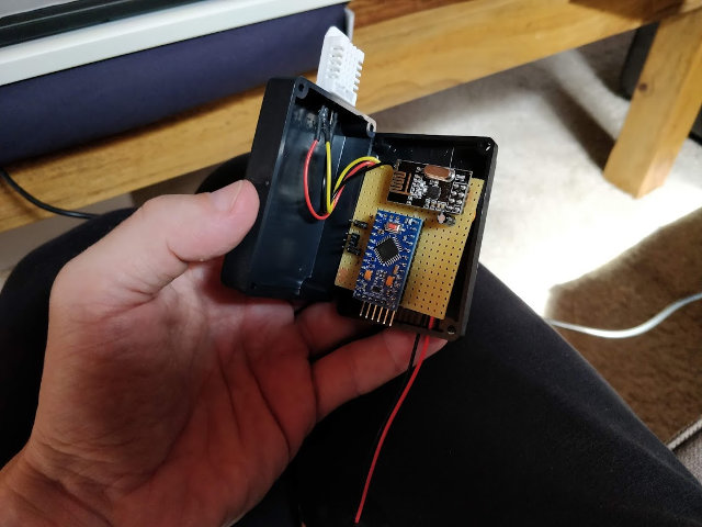
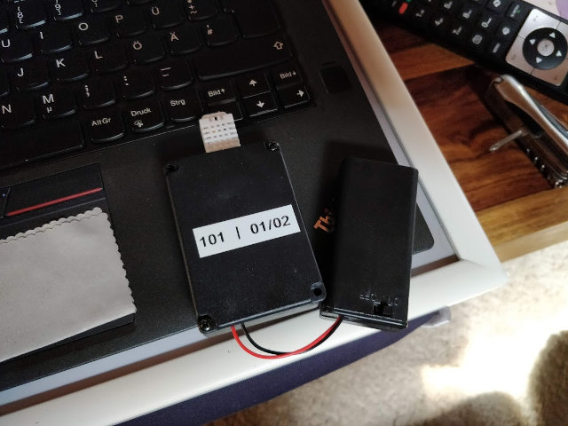
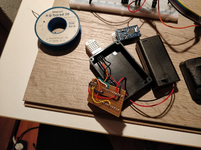
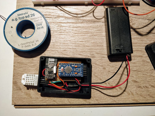
Both sensors are based on the modified MySensors.org sketch. The pro mini has modified hardware to cut energy consumption as suggested by Björns technik blog (German) by removing status LED and voltage converter.
Rev1 temp/hum sensor
Baseline-Sensor to test the whole setup. After first using the FTDI adapter to monitor the serial data generated in debug mode, the sketch is used “as is”, so every 60 seconds a touple of temp/hum values is pushed into the influxdb via MQTT. I did this to test if the reach of the nRF24 is enough for my purposes and also to get a rough idea how long two AA batteries could last.
To remind you: A pro mini operates on 3.3V and a single AA battery has 1.5V - used in serial and together, we’re just at 3V which is quite close to the BOD threshold of ~2.7V. The actual calculated value is 3.2V with two AA type batteries;
Note: I did not change the brown out detection fuse.
According to the spec the min Voltage at 8 MHz should be:
(( 2.7-1.8 )/2)+1.8 = 2.25 V
This is a nice value, but DHT22 and nRF24 need some more juice available, so brown out at the default 2.7V threshold should be fine. Therefore, in Rev2 there will be battery voltage detection.
Every measurement cycle lasts roughly 62 seconds, 60s cycle + 2s wait for the sensor to measure. This means:
24 * 60 * 60 = 86400 seconds a day 86400 / 62s intervals = ~1393 measurements a day
Based on these numbers, the sensor is running for 6 days straight, now. I’m planning to change the intervals to very 30 minutes. So we (again, roughly) get:
24*2 with half-hourly measurements = 48 measurements a day 1393 / 48 = ~29 days
Every day the sensor runs at the current (fast) measurement cycle gives us roughly 29 days of 30 minute timed measurements. Considering our current uptime of 6 days, we’re in for at least 174 days or half a year worth of measurements. Quite satisfactory, isn’t it?
Excerpt from the logfile:
2018-09-03 14:07:08.459 [vent.ItemStateChangedEvent] - DHT22_101_01_cellar_temp changed from 19.3 to 19.2
2018-09-03 14:09:11.974 [vent.ItemStateChangedEvent] - DHT22_101_02_cellar_hum changed from 77.9 to 77.8
2018-09-03 14:09:11.980 [GroupItemStateChangedEvent] - gHumidity changed from 68.0 to 67.9 through DHT22_101_02_cellar_hum
2018-09-03 14:10:07.490 [vent.ItemStateChangedEvent] - DHT22_102_02_pantry_hum changed from 58.0 to 57.9
2018-09-03 14:10:13.757 [vent.ItemStateChangedEvent] - DHT22_101_02_cellar_hum changed from 77.8 to 77.9
2018-09-03 14:11:15.526 [vent.ItemStateChangedEvent] - DHT22_101_02_cellar_hum changed from 77.9 to 78.3
2018-09-03 14:11:15.535 [GroupItemStateChangedEvent] - gHumidity changed from 67.9 to 68.1 through DHT22_101_02_cellar_hum
2018-09-03 14:12:17.328 [vent.ItemStateChangedEvent] - DHT22_101_02_cellar_hum changed from 78.3 to 78.2
2018-09-03 14:13:19.082 [vent.ItemStateChangedEvent] - DHT22_101_02_cellar_hum changed from 78.2 to 78.0
2018-09-03 14:13:19.087 [GroupItemStateChangedEvent] - gHumidity changed from 68.1 to 68.0 through DHT22_101_02_cellar_hum
Designing the actual sensor
As a first prototype, I used a breadboard with a directly soldered-on pro mini. To be able to program the arduino with my ISP programmer, I added a few pin-headers to connect the cable. I also soldered the nRF4 to the board. As casing, I used some ABS box where most of the stuff fits in without problems. One challenge is placing the two AAs somewhere. Four small holes for the DHT22 allow for measuring outside the box.


Problems/learnings from this design
I had massive problems with the signal strengh while placing the sensor inside the vaulted cellar. That’s around one meter of sandstone and concrete between sender and receiver. The next iteration in design will be another case, placed outside the cellar and a few cables connecting the sensor from within. I think, around one meter of length should suffice. My learnings from this design are:
- Having soldered on the arduino saves me some socket strips but having to provide a programming interface instead is more trouble, since you’ll have to look up the pin maps twice ;-)
- Using socket strips saves some breadboard space, too.
- Overall this allows for smaller casings, in the long run, too.
Rev2 temp/hum sensor
Next iteration for my sensor design: Socket strips, no capacitor for the nRF24 (had none left) and an improved sketch design. I’m still using the same ABS casing and external battery case. The sensor will be placed in the pantry: So I’ll able to tell when temperature levels are high enough for my bread rolls to be moved into the fridge.
Big thanks go out to @hggh for the battery measurement routine, based on the internal 1.1V reference.
Sketch is incremented to v2.0, since the refactoring into subroutines, adding battery level and a new message type are breaking changes.
// ...

#define CHILD_ID_VGE 2
int V_VGE;
// for later checking the battery status
byte ADCSRA_status;
const float InternalReferenceVoltage = 1.1;
short battery_status = 0;

// ...
MyMessage msgVoltage(CHILD_ID_VGE, V_VGE);

// ...

void presentation()
{
  // Send the sketch version information to the gateway
  sendSketchInfo("TemperatureAndHumidity", "2.0");

  // Register all sensors to gw (they will be created as child devices)
  present(CHILD_ID_HUM, S_HUM);
  present(CHILD_ID_TEMP, S_TEMP);
  present(CHILD_ID_VGE, V_VGE);

  metric = getControllerConfig().isMetric;
}

void setup()
{
  ADCSRA_status = ADCSRA;
  ADCSRA &= ~(1 << 7);
  power_adc_disable();

  // ...
}

void loop()
{
  // Force reading sensor, so it works also after sleep()
  dht.readSensor(true);

  handle_temperature();
  handle_humidity();
  read_battery_voltage();

  // Sleep for a while to save energy
  sleep(UPDATE_INTERVAL);
}

void read_battery_voltage()
{
  power_adc_enable();
  ADCSRA = ADCSRA_status;
  ADCSRA |= bit (ADPS0) |  bit (ADPS1) | bit (ADPS2);  // Prescaler of 128
  ADMUX = bit (REFS0) | bit (MUX3) | bit (MUX2) | bit (MUX1);

  delay(10);
  bitSet (ADCSRA, ADSC);
  while (bit_is_set(ADCSRA, ADSC)) {
  }
  float battery_voltage = InternalReferenceVoltage / float (ADC + 0.5) * 1024.0;

  ADCSRA &= ~(1 << 7);
  power_adc_disable();

  if (isnan(battery_voltage)) {
    Serial.println("Failed reading battery_voltage");
  } else {
    #ifdef MY_DEBUG
    Serial.print("V: ");
    Serial.println(battery_voltage);
    #endif

    send(msgVoltage.set(battery_voltage, 1));
  }
}

void handle_temperature()
{
  // ...
}

void handle_humidity()
{
  // ...
}
This sketch will introduce a third subnode ID in concert with a new message type (derived from the default message), based on MySensors framework. With this third message type, the current calculated voltage is transmitted to openhab2.

